IDO-1000
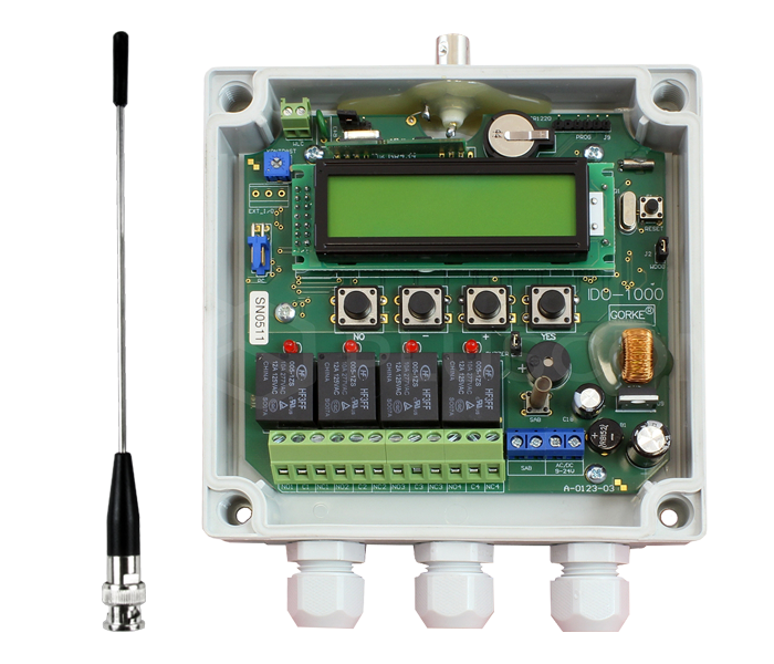
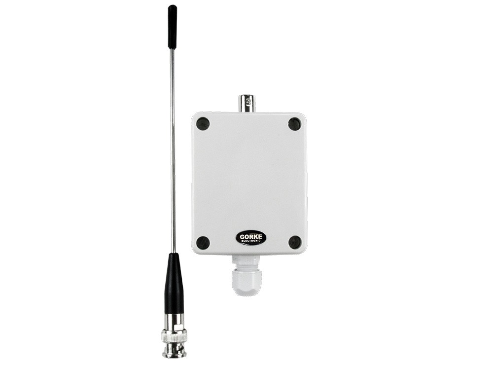
The estate’s shared receiver: two channels control the entry and exit gates, the third receives alarms from the houses. Memory for 1,000 transmitters, four relays, individual deletion.
Quantity: 1
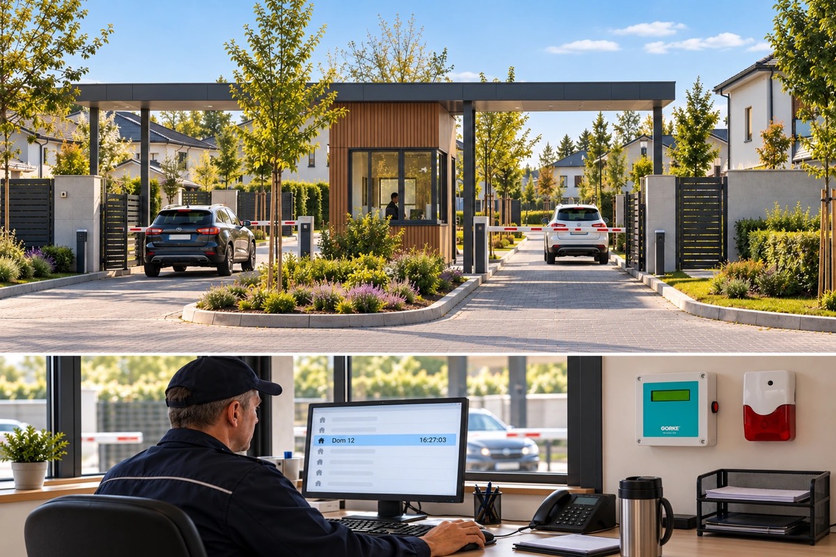
A housing estate with round-the-clock security: one identification receiver controls the entry and exit gates and, at the same time, receives alarm signals from the panels in the houses and passes them to the security room.
01 / Investment context
The estate has 86 houses, and about 400 people are authorised to drive in and out. It has round-the-clock security, an entry gate and an exit gate. Residents must be able to open both gates themselves with a remote control, and the security room must learn in which house an alarm has gone off.
The houses have their own alarm panels, but an alarm in one of them does not tell security which house it comes from — a guard would first have to work that out. The association therefore wanted a second notification path: from the panel of the property concerned to the estate’s security room, identifying the specific house — even when the guard is on patrol rather than in the security room.
Shared equipment is paid for by all the properties, so it mattered that one system should handle both the gates and the alarms, rather than two separate sets of equipment to buy and maintain.
The investor’s goal: Gate access and a second alarm notification path in one system: residents open the gate with a remote, and the security room knows at once which house the alarm came from.
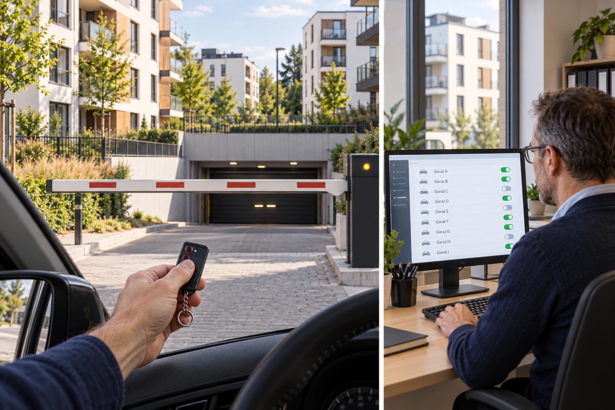
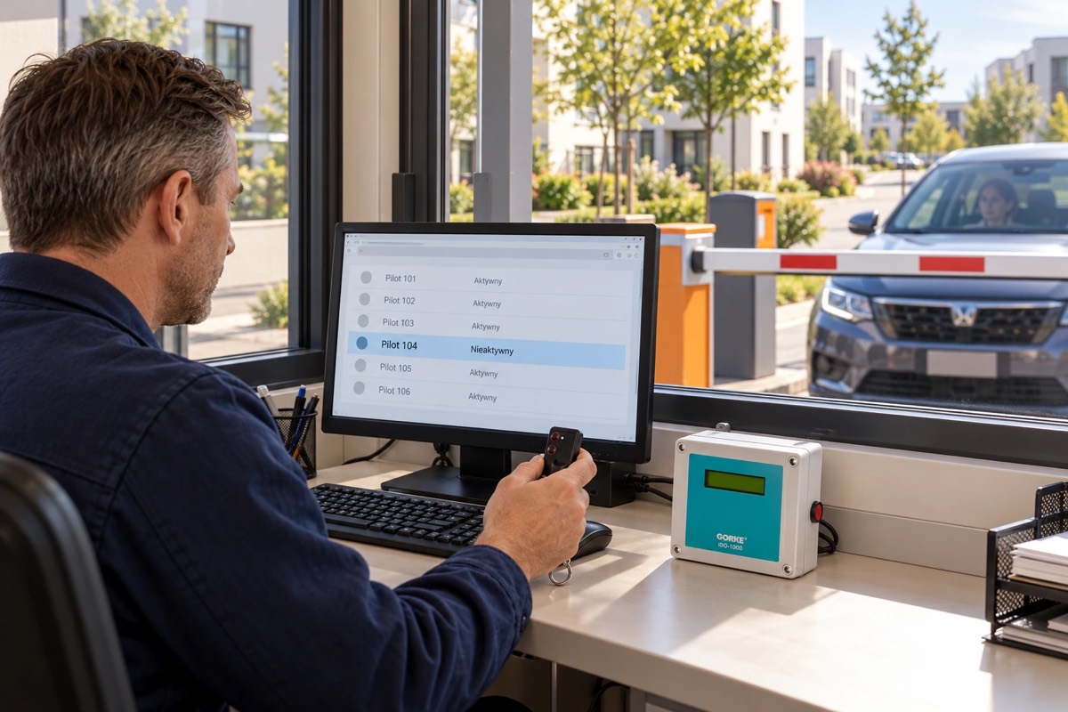
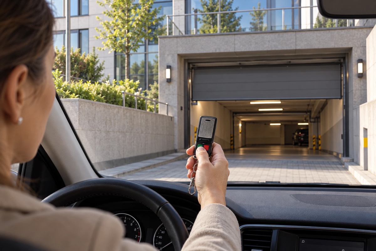
The basis is a single identification receiver (IDO-1000) that handles both tasks. Two of its channels control the gates: each resident receives a two-button remote (today the PUK-102) — one button opens the entry gate, the other the exit gate. The channel relay works in monostable mode and sends a signal to the drive’s control input for 20 seconds.
The third channel is used to monitor alarms. The alarm panels on the properties were extended with a transmitter (NRP-102) that starts transmitting when the panel applies voltage to it. The receiver recognises which transmitter has sent, and the Tablica Synoptyczna software (today SPA-1000/PR) on the computer in the security room shows which house the alarm came from and stores the event in its archive. At the same time the third channel’s relay switches on an outdoor light-and-sound signal unit, placed where the guard on patrol can see it.
About 400 remotes plus one transmitter per house with a panel — at most 86 — fit into the receiver’s memory of 1,000 transmitters. The receiver deletes transmitters individually, so a lost remote is removed without touching the others. Pager notification for the security staff (today with the OBI-4SH pager) would complement the system, but the investor decided against it.
02 / Operating principle
One receiver handles the estate’s gates and the alarms from the houses. Every signal goes to the right channel.
01 / Signal source
NRP-102 Transmitter at the house’s alarm panelSends the alarm from the property to the shared system.
02 / Reception
IDO-1000 Shared receiverIdentifies the source and handles the alarm channel.
03 / Notification
Security Two alarm points Security room + Signal unitShown on screen, and an alarm the guard on patrol can see.
Security knows which house the alarm came from. The software points to the property and logs the event; the signal unit alerts the guard on patrol.
01 / Signal source
Resident’s remote Two-button remoteOne button opens the entry gate, the other the exit gate.
02 / Reception
IDO-1000 Shared receiverIdentifies the remote and handles the gate channel.
03 / Action
Gate Entry or exitThe channel’s relay signals the gate operator’s input for 20 seconds.
Residents open the gate themselves with a remote. The receiver knows each remote individually, so a lost one is deleted without touching the others.
A simplified functional diagram.
03 / Installation components
The models used in the project, with their equivalents in the current range.
The estate’s shared receiver: two channels control the entry and exit gates, the third receives alarms from the houses. Memory for 1,000 transmitters, four relays, individual deletion.
Quantity: 1
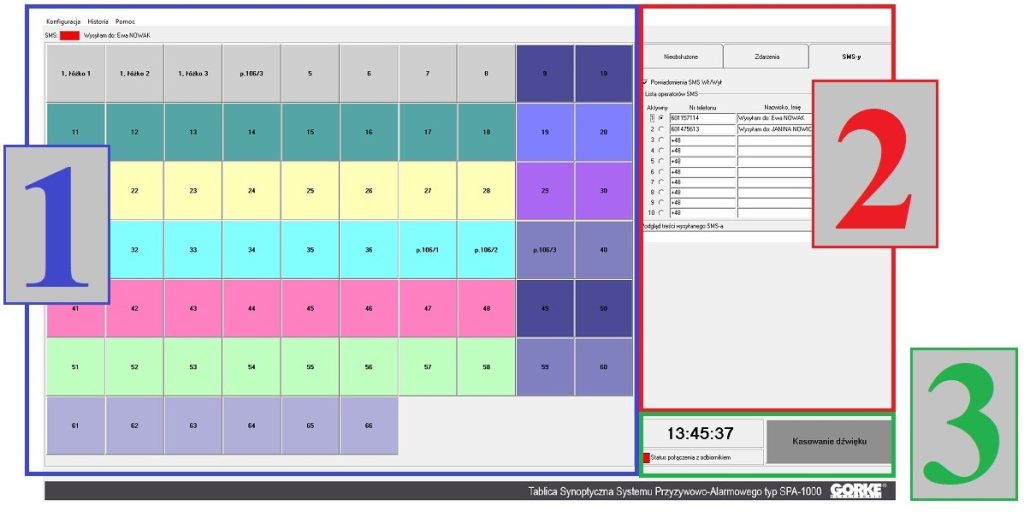
Tablica Synoptyczna software on the security room computer — today’s version of the software used in this project: shows which house the alarm came from and keeps an event archive.
Quantity: 1
Transmitter at the house’s alarm panel, powered from its 12 V DC output: it starts transmitting when the panel applies voltage. Range up to 1,000 m with a receiver fitted with an H2 module.
Quantity: 1 per house with a panel
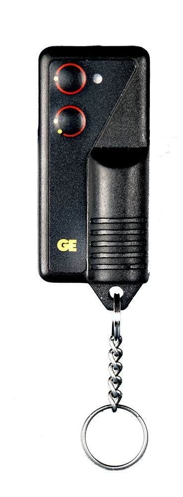
Resident’s 2-button remote — today’s model of the two-button remote used in this project: one button for the entry gate, the other for the exit gate.
Quantity: approx. 400
Outdoor signal unit switched by the receiver’s third-channel relay: the guard on patrol sees and hears that an alarm has come in.
Quantity: 1
An option the investor did not choose at the time: a pager for the security guard. The alarm reaches the guard even where the signal unit cannot be seen.
Quantity: optional
Catalogue figures describe a device under stated conditions, usually in open terrain, and are not a guaranteed range in every installation. Device quantities in the examples are indicative.
04 / Value for the investor
The gates and the alarms are handled by the same receiver and software, whose cost is spread over all the properties; the transmitter at the panel and the remotes are paid for by individual residents.
The security room sees the house and the time of the alarm on screen, and the archive keeps every event — no searching the estate for the source of the signal.
The outdoor signal unit tells a guard who is not in the security room at that moment that an alarm has occurred somewhere and the house needs to be identified.
05 / Before installation
Before devices are chosen, what matters is the site’s conditions and how the system ties into the final installation.
Source: an archived GORKE description of the installation. For a new investment we choose current models.
More from this sector
Housing and property
A housing estate in Katowice: one remote control opens the shared barrier and the car park gate of the resident’s part of the estate, and the investor manages the rights of more than 2,000 remotes over the IP network.
Housing and property
A proposal for a car park with several hundred subscribers and high turnover: remotes blocked for non-payment, lost ones deleted, and an event archive with customer data — all in one program.
Housing and property
An office building with Wiegand access control: the receiver at the barrier works like another reader, the tenant’s remote control like a card, and the rights stay in the system the property manager already uses.
A project for your site
Send us the key requirements — GORKE will help define the scope, the technology and the components that fit the investment.