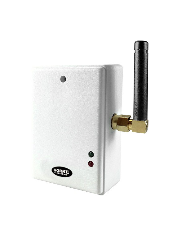
NBX-102
LX transmitter at the compressor controller: two NC inputs for the fault and pressure-drop contacts, plus a housing tamper circuit. Battery-powered, range up to 4 km in open terrain.
Quantity: 1
An LX transmitter at the compressor controller, a receiver with a signal unit in the maintenance office, and a GSM transmitter that texts the person on call — at night and at weekends too.
01 / Investment context
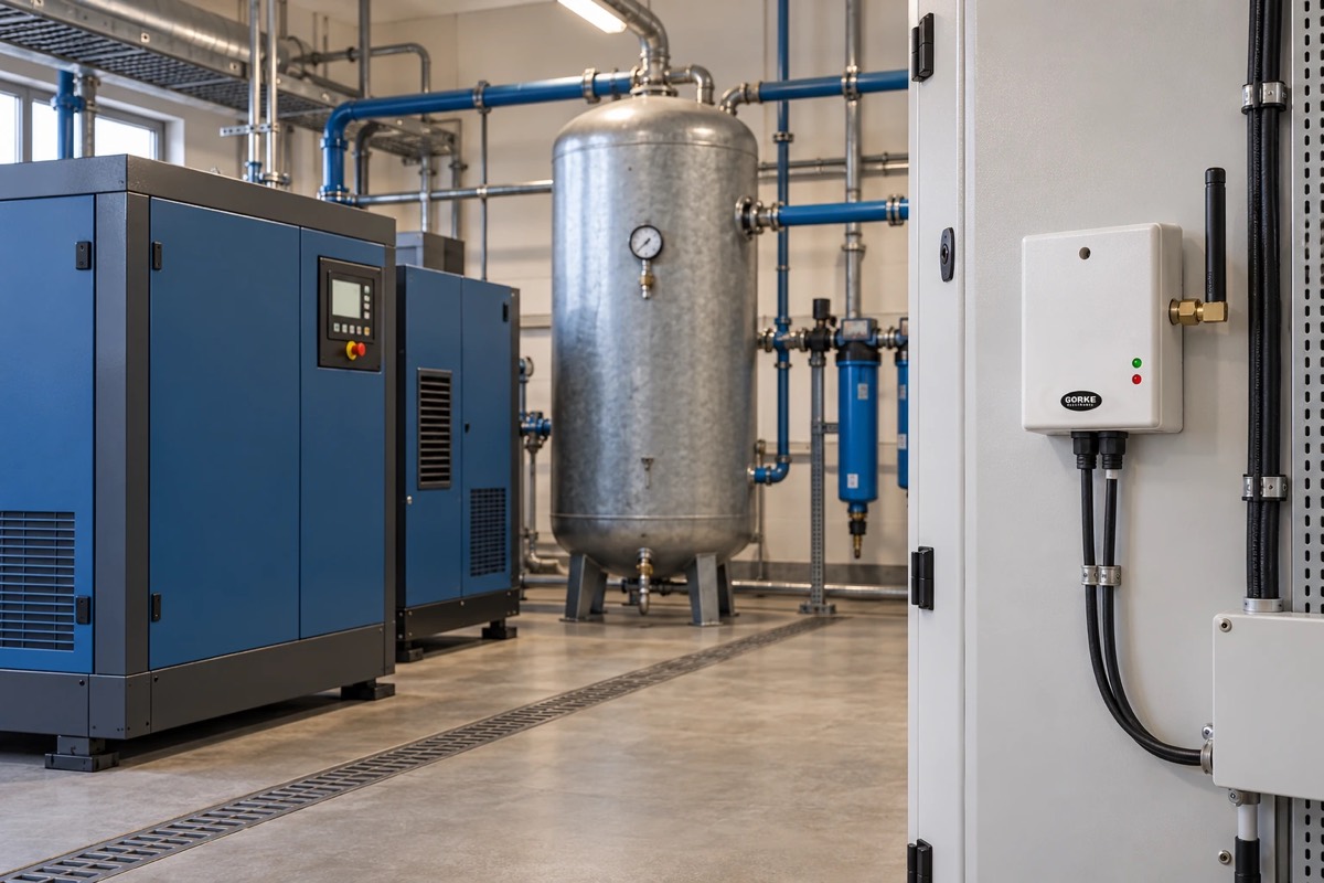
The compressors supply compressed air to production, yet they stand in a separate building 300 m from the maintenance office, behind a steel-framed hall. The compressor controller provides alarm contacts — compressor fault and pressure drop — but nobody sees them, because nobody normally works in the compressor house.
A cable across the site means trenching, crossings under internal roads and disruption to traffic, and an ordinary radio link may not get through a steel hall. After hours a fault only comes to light in the morning, when the pressure in the network has dropped and the lines are standing — and then losses are counted in hours of downtime rather than minutes of repair.
The investor’s goal: Each of the controller’s two alarm states known at once: in the maintenance office by day, and on the on-call phone at night and at weekends.
The controller’s alarm contacts — compressor fault and pressure drop — are wired to the two NC inputs of a battery-powered LX transmitter (NBX-102) mounted next to the controller. When a contact opens, the transmitter sends the event using LoRa modulation, designed to work where an ordinary radio link fails, and the receiver confirms each transmission back to it. A range test decides whether the signal reliably gets past the steel hall.
In the maintenance office each alarm state switches one of the two relays of an LX receiver (RSX-K02). Both relays switch on a signal unit with volume control (SWR-108) and feed the state to the inputs of a GSM transmitter in a housing with a power supply (ATG-SG4set), which sends a text with its own wording for each state. Because each output drives two devices, a relay module (MPU-121) on each channel separates the GSM input.
The on-call numbers and message texts are set from a computer with a programming cable (K-5). The receiver, the signal unit and both modules run on a 12 V DC power supply in the office. An LX confirmation only means that the transmission has reached the receiver — only the controller shows the state of the compressors.
02 / Operating principle
The compressor controller’s two alarm states travel by LX radio to the maintenance office, and from there by text to the person on call.
01 / Signal source
Compressor house Compressor controller contactsA compressor fault or a pressure drop opens an alarm contact.
02 / Transmission
LX link 300 m, with a steel hall in betweenThe transmitter at the controller sends the state, and the receiver in the office confirms receipt.
03 / Notification
Maintenance Maintenance office and on-call phone Signal unit + Text messageEach state switches on the signal unit and sends a text with its own wording to the person on call.
A compressor fault is known at once, at night too. The person on call receives a text moments after the contact opens — before the pressure drop stops the production lines.
A simplified functional diagram.
03 / Installation components
An example selection — the number of devices depends on the site.
LX transmitter at the compressor controller: two NC inputs for the fault and pressure-drop contacts, plus a housing tamper circuit. Battery-powered, range up to 4 km in open terrain.
Quantity: 1
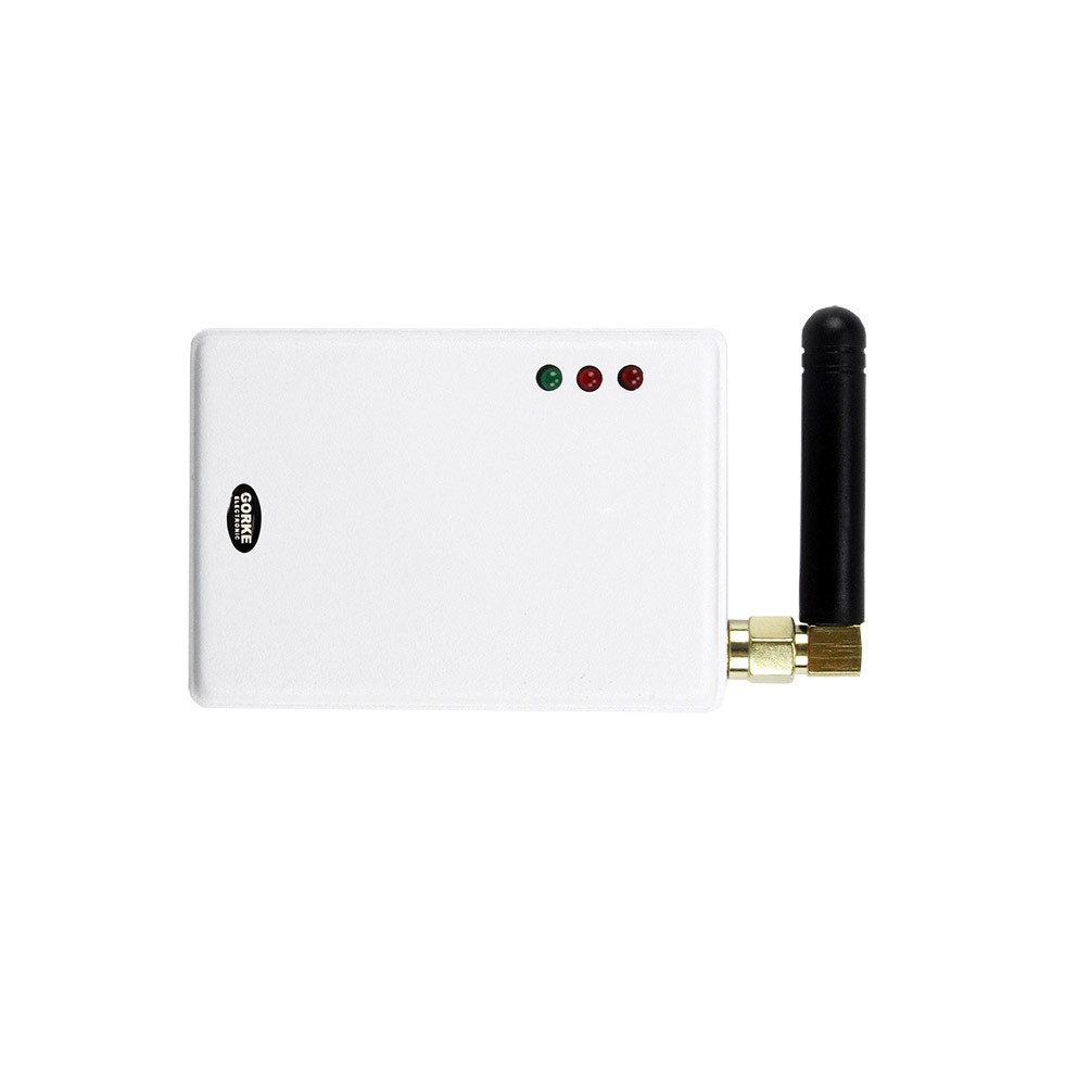
LX receiver in the maintenance office: each alarm state switches one of the two NO/NC relays, and the transmitter gets a receipt confirmation for each transmission. 12 V DC supply.
Quantity: 1
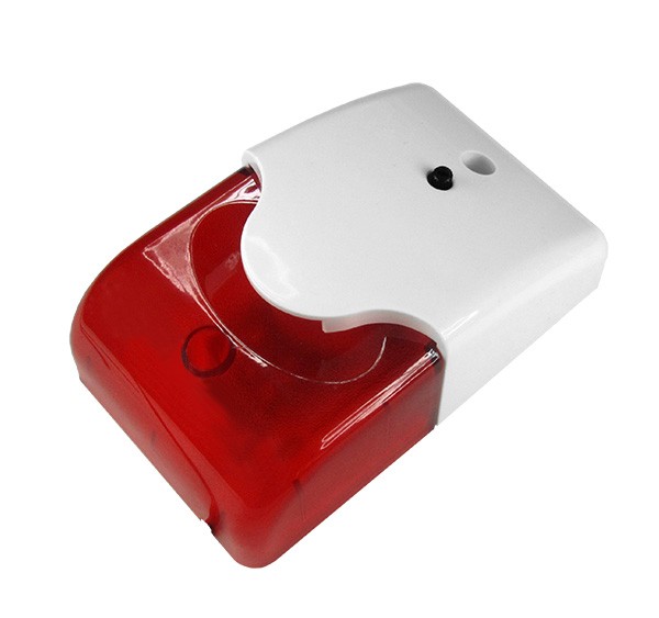
Light-and-sound signal unit in the maintenance office with a volume knob: the alarm is clearly audible without drowning out the office’s work. 12 V DC.
Quantity: 1
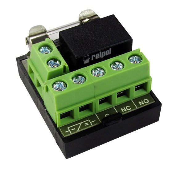
Relay module next to the receiver, one per channel: separates the GSM transmitter’s input from the signal unit circuit, so that the same state switches on the signal unit and reaches the GSM input.
Quantity: 2
GSM transmitter, 2G/4G/LTE, in a housing with a power supply: each of the two states fed to an input sends a text or a CLIP call to the maintenance staff on call.
Quantity: 1
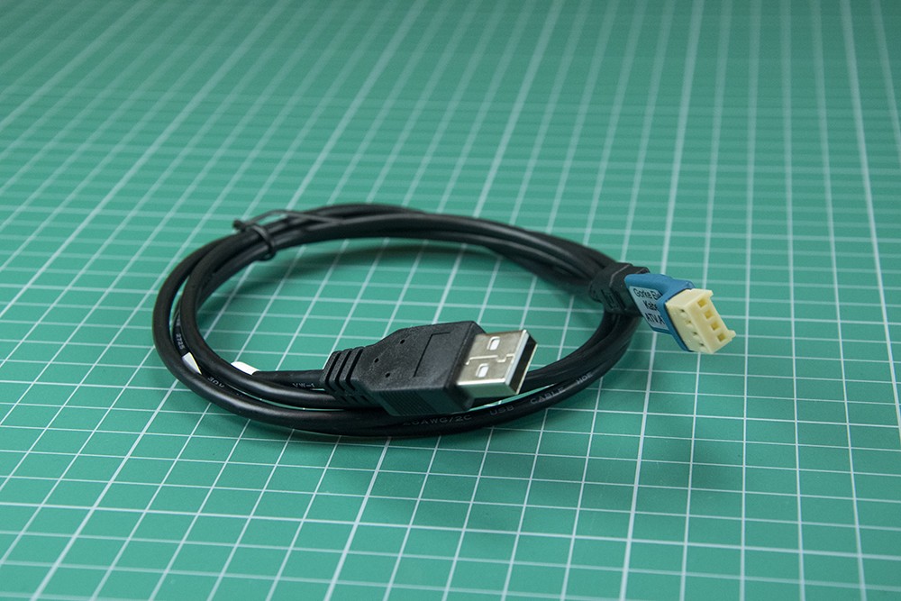
Cable for programming the GSM transmitter from a computer: on-call numbers, message texts and input assignment. Needed at commissioning.
Quantity: 1
Power supply in the maintenance office for the LX receiver, the signal unit and both relay modules — all of them run on 12 V DC.
Quantity: 1
Catalogue figures describe a device under stated conditions, usually in open terrain, and are not a guaranteed range in every installation. Device quantities in the examples are indicative.
04 / Value for the investor
The person on call receives a text moments after the contact opens, at night and at weekends too — before the pressure drop stops the production lines.
LX radio carries both states across the site without a cable, crossings under internal roads or disruption to traffic.
The receiver confirms every transmission to the transmitter — the link is two-way, so the transmitter does not send blind as with an ordinary radio link.
05 / Before installation
Before devices are chosen, what matters is the site’s conditions and how the system ties into the final installation.
Example configuration — it needs a technical selection for your site.
More from this sector
Industry
A precast concrete plant: a worker calls a forklift from the workstation, and the operator knows where the call came from — without extensive cabling across the hall.
Industry
An assembly line with 20 workstations: two buttons at each one separate breakdowns from material shortages, and Tablica Synoptyczna logs the time from call to cancellation.
Industry
A 20-hectare plant site: a security guard calls for backup with one key, feels the confirmation vibrate, and the guardhouse sees who is calling.
A project for your site
Send us the key requirements — GORKE will help define the scope, the technology and the components that fit the investment.