SPR-PK1/A/BAT/PT
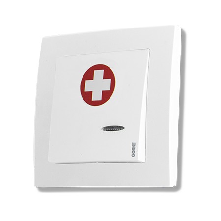
Call button at the bed, in a wall frame within the resident’s reach. Battery-powered, so no power has to be run to every room.
Quantity: 1 per bed
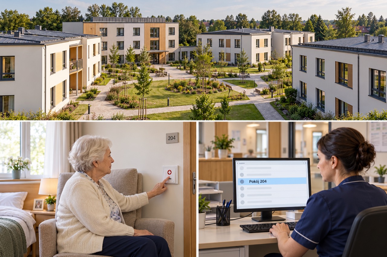
A nurse call system for a complex of four buildings with about 200 residents: thirteen gateways serve the areas of the installation, IP communication links the parts of the site, and calls from rooms and bathrooms reach the staff’s panels and pagers.
01 / Investment context
The social care home occupies a complex of four buildings with about 200 residents. One of them is a three-storey administrative and social wing. Residents have 150 rooms and 120 bathrooms, and they must be able to call staff from both places — from the room and from the bathroom.
Carers do not work in one place: they move between wards. In a site like this, a call that can only be heard at one nurses’ station or in one corridor is easy to miss. And “someone is calling” is not enough — with four buildings, a carer must know at once which room or which bathroom the call came from, so that no time is lost searching.
The investor’s goal: Every call from a room or bathroom should show where it came from and reach the staff member nearest to the resident — even while they are moving between wards.
The installation is divided into areas. Each is served by one of thirteen gateways, which receives the calls from the buttons in its part of the site. IP communication links the parts of the site, so the four buildings form one system. Calls appear on four operator panels showing where they came from and are passed on to 20 pagers that the staff carry with them.
The solution was adapted to the layout of the buildings and the way the staff work. The system shows where the call came from and can pass the information to the staff member nearest to the resident — even while they are moving between wards. Staff learn of a call wherever they happen to be, not only at a panel.
In GORKE’s 2026 range, such a system is made up of bedside buttons (SPR-PK1/A/BAT) and pull-cord transmitters with an SOS key in the bathrooms (SPR-PC2/AA/BAT), IP gateways (SPR-IPB/R2/K) and operator panels with a display (SPR-IPP), powered by PoE or 6–24 V, and staff pagers (OBI-4SH). Optionally, the synoptic board software (SPA-IP2) also shows the calls on a Windows 11 computer.
02 / Operating principle
Calls from rooms and bathrooms in four buildings reach the operator panels and the staff’s pagers.
01 / Signal source
Button 150 rooms and 120 bathroomsThe resident calls staff from the room or the bathroom.
02 / Reception
Area gateway One of 13 on the siteReceives the calls from its part of the site; IP communication links the buildings.
03 / Notification
Staff 4 panels and 20 pagers Panels + PagersThe panels show where the call came from, and the information also goes to the pagers.
The call is passed to the staff member nearest to the resident. Staff learn of a call wherever they happen to be — even while moving between wards.
A simplified functional diagram.
03 / Installation components
The description of the installation names no models — this is GORKE’s choice for a similar site.
Call button at the bed, in a wall frame within the resident’s reach. Battery-powered, so no power has to be run to every room.
Quantity: 1 per bed
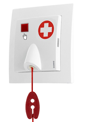
Pull-cord transmitter in the bathroom: a call by the cord or by the SOS key — whichever is within reach. Battery-powered.
Quantity: 1 per bathroom
Area IP gateway: receives calls from GORKE 433.92 MHz transmitters in its part of the site and passes them on over the IP network. Powered by PoE or 6–24 V AC/DC.
Quantity: 13
Operator panel with an OLED display and four keys: shows staff where the call came from. Powered by PoE or 6–24 V AC/DC.
Quantity: 4
Staff pager: the call reaches the staff member even on the way between wards. Charged by USB or wirelessly (Qi).
Quantity: 20
Synoptic board software for the IP System on a Windows 11 computer — calls from the whole site on one screen.
Quantity: optional
Catalogue figures describe a device under stated conditions, usually in open terrain, and are not a guaranteed range in every installation. Device quantities in the examples are indicative.
04 / Value for the investor
The system shows the room or bathroom, so across four buildings the carer goes straight to the right place without touring the wards.
The call is passed to the staff member nearest to the resident, so staff do not have to watch the panels so as not to miss a call.
IP communication links the parts of the site, so the four buildings are served by one nurse call system with one way of handling calls.
05 / Before installation
Before devices are chosen, what matters is the site’s conditions and how the system ties into the final installation.
Source: the description of the installation under Custom projects.
More from this sector
Care and health
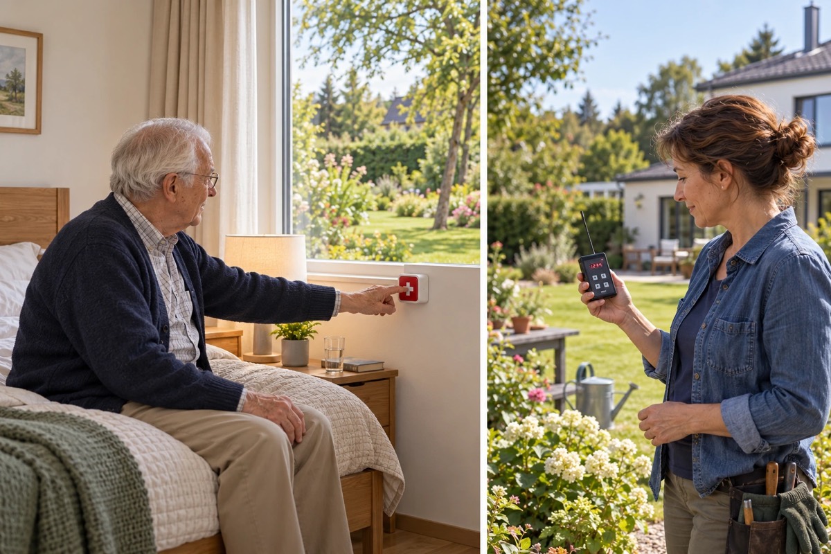
Home care: a large button with a tactile flap or a wrist transmitter sends the call straight to the carer’s pager — no control unit, no installation, in a single-family house.
Care and health
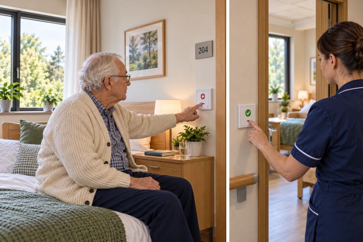
A care home with 32 rooms: a call from the bed or the bathroom shows above the door, at the nurses’ station and on the pager, and ends only at the resident’s side.
Care and health
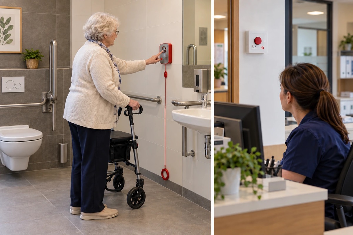
A clinic on two floors: a patient calls for help from an accessible toilet by key or pull cord, reception knows which toilet, and the call is cancelled at the patient’s side.
A project for your site
Send us the key requirements — GORKE will help define the scope, the technology and the components that fit the investment.