TdN-01
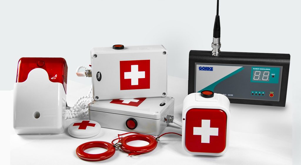
Accessible-toilet kit: a button and a pull-cord transmitter with cancel key, a signal unit above the door and an identification receiver at the porter’s lodge, shared by the whole system.
Quantity: 1
One 433.92 MHz receiver at the porter’s lodge for the customer service office and the accessible toilet: a toilet kit, under-counter buttons at six desks and a signal unit for the porter.
01 / Investment context
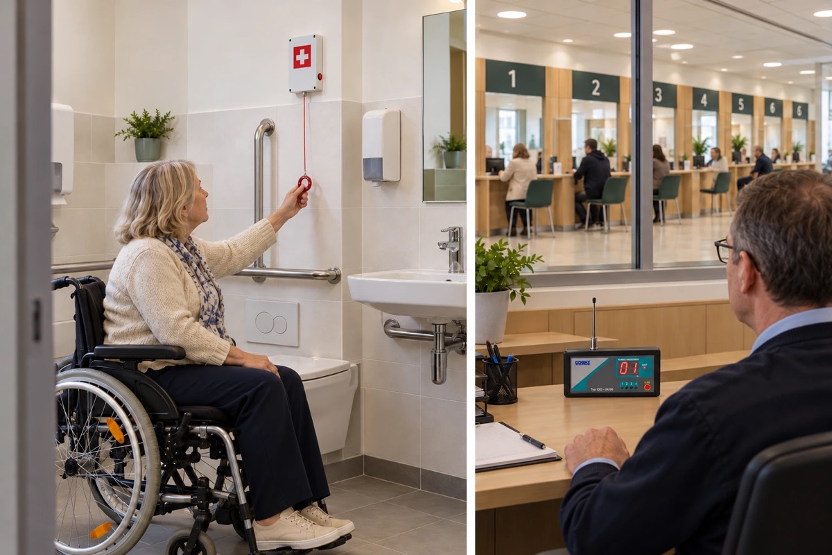
In the municipal office, the customer service office has six desks, with a toilet for people with disabilities next to it. An accessible toilet needs a way to call for help: a visitor who feels faint or falls behind a closed door must be able to signal with one movement, and someone must come to them.
At the desks the problem is different. A conversation with a visitor sometimes gets out of hand, and the clerk wants to call the manager or the municipal police — but without the visitor noticing, because a raised voice or reaching for the phone can make things worse. The office does not want to run two separate systems for these two needs.
The investor’s goal: One receiver at the porter’s lodge for the toilet and the desks: the porter sees the number of the spot and acts according to procedure, while the visitor at the desk does not see the call.
The toilet is covered by a toilet kit (TdN-01): a button with cancel key (PNH-201C) and a pull-cord transmitter with cancel key (PNH-201SC) in the toilet, a signal unit above the door on the corridor side and an identification receiver (IDO-04/99) at the porter’s lodge. The toilet transmitters repeat the call every 30 seconds until someone cancels it with the button on the spot — so a call from the toilet ends at the visitor’s side.
Each of the six desks has a call button under the counter (PNP-202), programmed into the same receiver but not into the signal unit by the toilet — nothing lights up and nothing sounds in the service hall. The receiver shows the transmitter’s number, and a list next to it gives the place: “1–6 — desks, 7 and 8 — toilet”. The receiver’s relay switches on a signal unit with adjustable volume at the porter’s lodge (SWR-108).
The receiver, the signal unit at the porter’s lodge and the signal unit above the toilet door run on 12 V DC from the system’s power supplies (SPR-ZS1). If the manager of the service hall is to receive calls from the desks directly, they can carry a pager (OBI-4SH) programmed only for the under-counter buttons, in which each desk is a separate zone.
02 / Operating principle
Calls from the accessible toilet and six desks reach one receiver at the porter’s lodge, with the number of the spot.
01 / Signal source
Toilet Button and pull-cord transmitterThe visitor calls for help with the button or the pull-chain.
02 / Reception
IDO-04/99 Receiver at the porter’s lodgeNumber 7 or 8 on the display — the list says that is the toilet.
03 / Notification
Signal Units At the lodge and above the door Porter’s lodge + CorridorThe porter hears the call, and the signal unit above the toilet door switches on.
A call from the toilet ends at the visitor’s side. The transmitters repeat the call every 30 seconds until someone cancels it with the button on the spot.
01 / Signal source
PNP-202 Under-counter button at the deskThe clerk calls for support with a hand movement the visitor cannot see.
02 / Reception
IDO-04/99 Receiver at the porter’s lodgeNumbers 1–6 point to the desk; nothing lights up in the service hall.
03 / Notification
Porter Calls the manager or the municipal policeHears the call from the signal unit at the lodge and responds according to procedure.
The visitor at the desk does not see the call. The under-counter buttons do not trigger the signal unit by the toilet; the hall manager can carry a pager set to them alone.
A simplified functional diagram.
03 / Installation components
An example selection — the number of devices depends on the site.
Accessible-toilet kit: a button and a pull-cord transmitter with cancel key, a signal unit above the door and an identification receiver at the porter’s lodge, shared by the whole system.
Quantity: 1
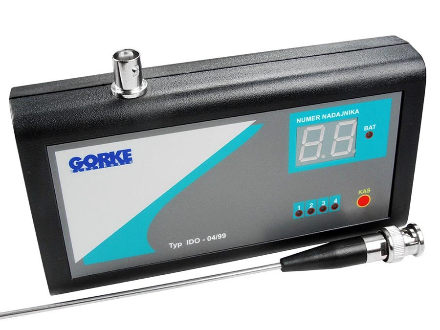
The kit’s identification receiver, at the porter’s lodge: stores the eight transmitters of the toilet and the desks, shows the number of the one calling and switches on the signal unit through its relay.
Quantity: included in TdN-01
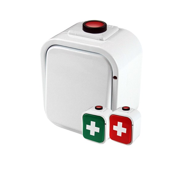
Button in the toilet: the call repeats every 30 seconds until someone cancels it on the spot with the cancel key.
Quantity: included in TdN-01
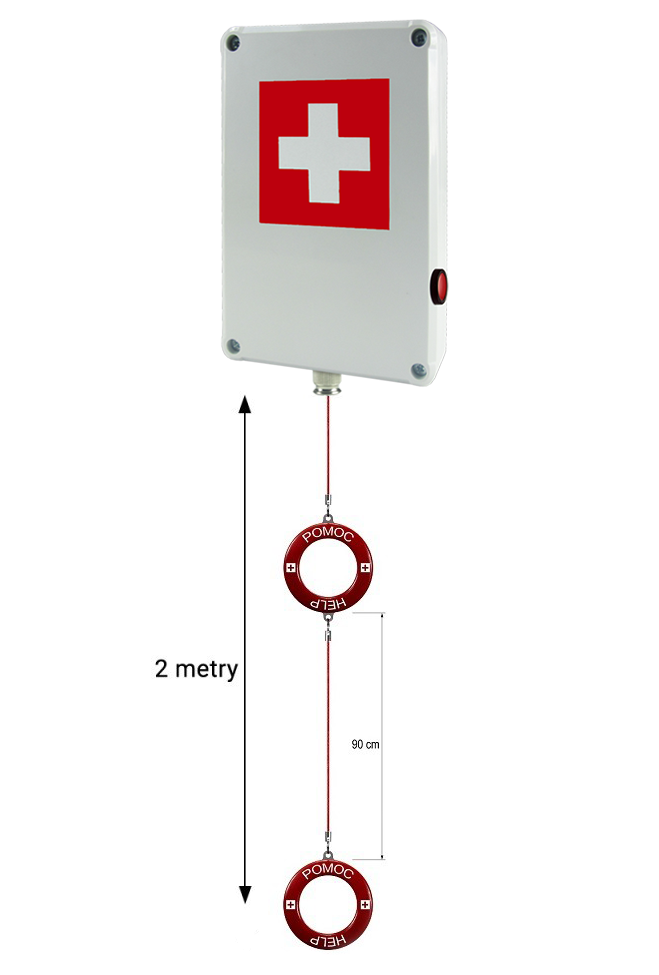
Pull-cord transmitter in the toilet with a 2 m chain: the call repeats every 30 seconds until it is cancelled on the spot.
Quantity: included in TdN-01
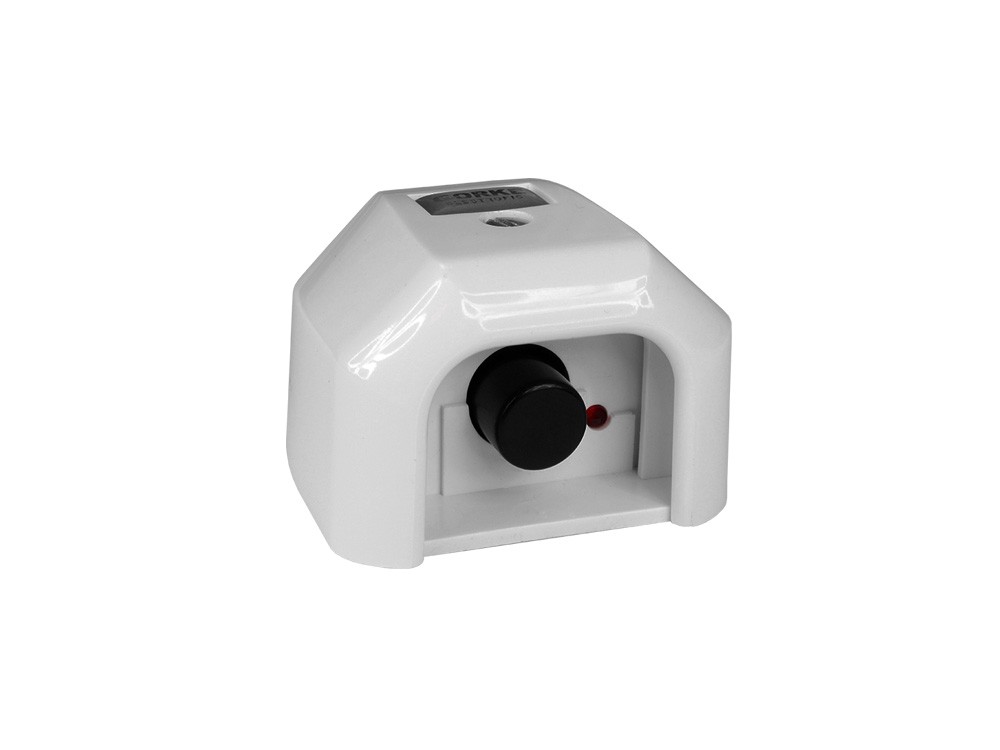
Button under the service desk counter: the clerk calls for support with a hand movement the visitor cannot see. Battery-powered.
Quantity: 6
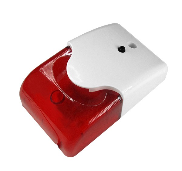
Light-and-sound signal unit at the porter’s lodge, switched by the receiver’s relay; the volume is set with a knob on the front panel.
Quantity: 1
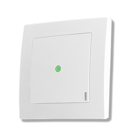
Mains power supply, 230 V AC: one at the porter’s lodge for the receiver and signal unit, the other by the toilet door for the signal unit above the entrance.
Quantity: 2
Pager for the manager of the service hall, programmed only for the under-counter buttons: a call from a desk reaches them directly, with the desk’s zone number.
Quantity: optional
Catalogue figures describe a device under stated conditions, usually in open terrain, and are not a guaranteed range in every installation. Device quantities in the examples are indicative.
04 / Value for the investor
Calls from the toilet and the six desks go to one receiver at the porter’s lodge — one point of response, one maintenance check, one procedure.
The button is under the counter and nothing lights up in the service hall — the clerk asks for support without raising their voice or escalating the conversation.
The number on the display points to the toilet or a specific desk, so support goes straight to the right place.
05 / Before installation
Before devices are chosen, what matters is the site’s conditions and how the system ties into the final installation.
Example configuration — it needs a technical selection for your site.
More from this sector
Public buildings and events
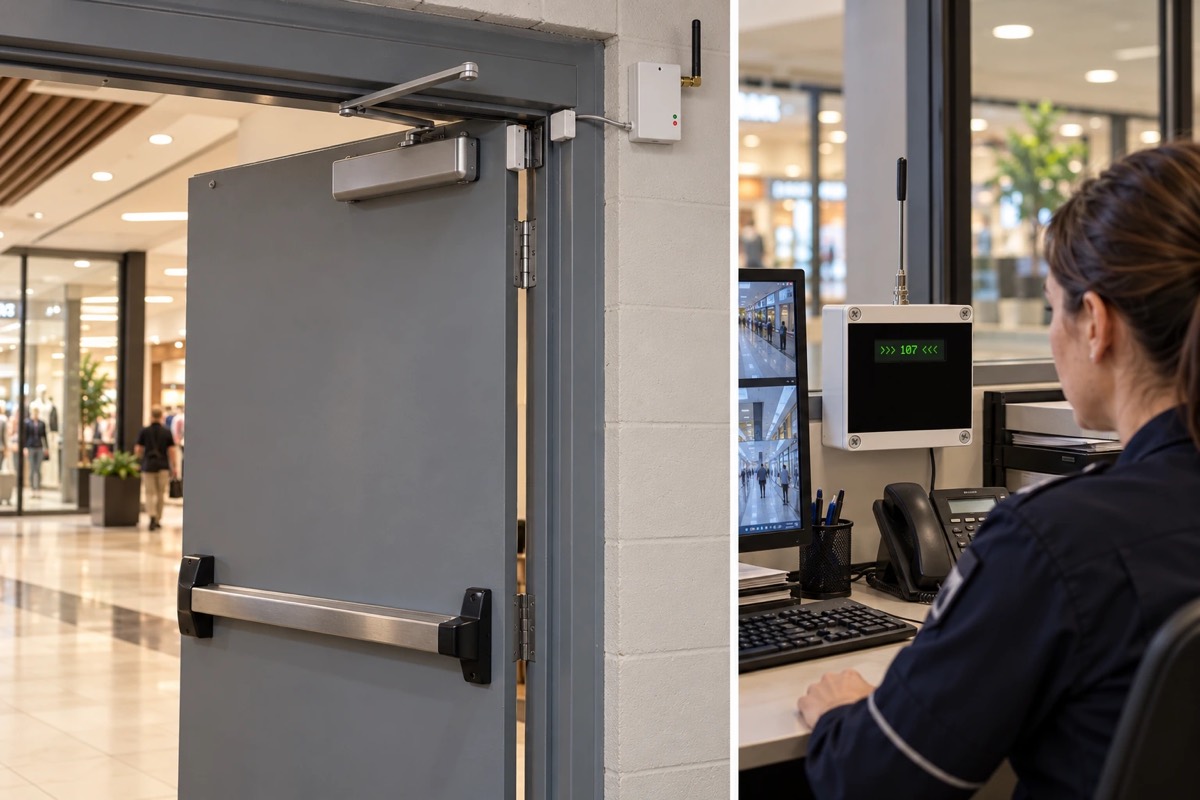
A shopping centre on several storeys: reed contacts and LX transmitters report the opening of 5 fire doors to the monitoring centre until they are closed.
Public buildings and events
The gold panning competition in Złotoryja: competitors’ stations, the judges’ station, a control point and a results board linked by radio, with times measured to 0.01 s.
Public buildings and events
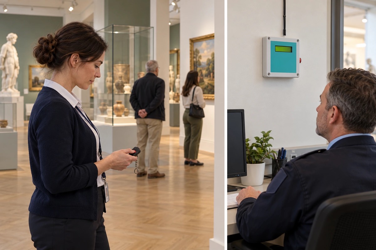
A museum with 14 rooms on two floors: the room attendant calls security with a key fob, and the security desk and the staff on patrol see which room it is.
A project for your site
Send us the key requirements — GORKE will help define the scope, the technology and the components that fit the investment.