NRP-102K
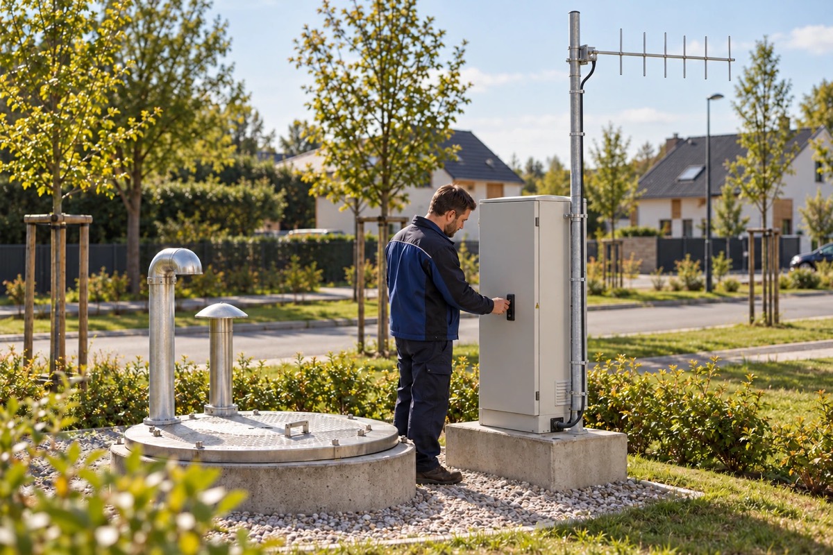
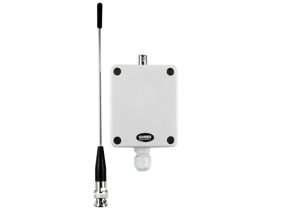
Transmitter with link supervision in the pumping station, 12 V DC, IP66. Input 1: high level from the float switch, input 2: pump fault from the protection contact.
Quantity: 4
Radio alarm transmission with link supervision for pumping stations under viaducts and next to housing estates, 0.4–1.6 km from the depot: the receiver at the depot tells an alarm from a lost link and from a transmitter without power.
01 / Investment context
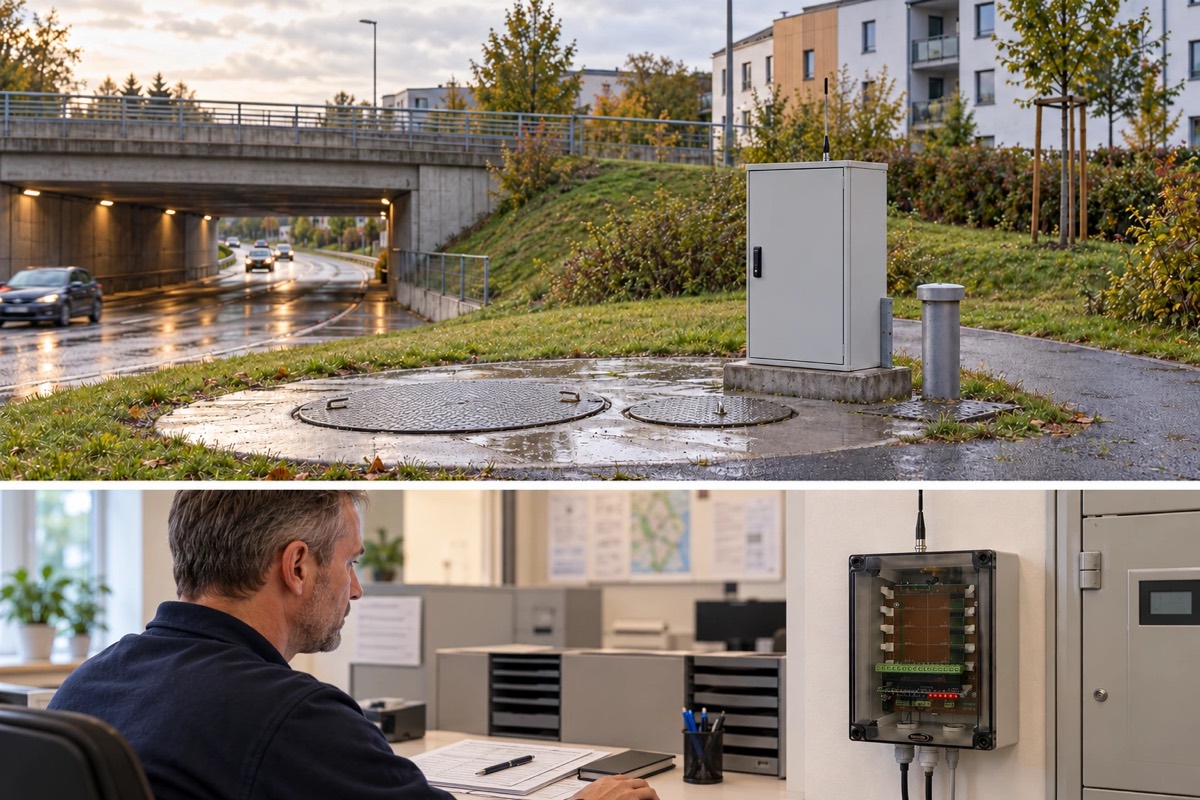
The municipal utility maintains four stormwater pumping stations — under viaducts and next to housing estates, 0.4 to 1.6 km from its depot. They run automatically, and on a normal day nobody attends them on site.
In a downpour time matters: if a pump stops or the level rises above the threshold, water floods the underpass beneath the viaduct or the cellars on the estate. High-level and pump-fault signals from every site must reach the depot, and after hours the on-call worker in the field as well.
Silence is the greatest danger. If the link to a pumping station breaks during a storm, the absence of an alarm must not be taken as “all is well”. The utility also wants to add further sites without replacing the equipment at the depot.
The investor’s goal: Tell an alarm from a lost link, alert the on-call worker after hours, and add further pumping stations without replacing the receiver.
Each pumping station has a transmitter with link supervision (NRP-102K), powered at 12 V DC with battery backup. Input 1 is high water level from a float switch, input 2 a pump fault from the protection contact. The transmitter also sends link and power supervision signals.
At the depot a receiver with link supervision (RP10-2K) handles two sites, and an expansion module (RP-10M) adds two more. From each pumping station the receiver gets both states and monitors the link and the transmitter’s power — it reports a broken link just like an alarm. Further modules extend it to 10 sites.
The signal from the farthest pumping station, 1.6 km from the depot, is carried by a repeater with link supervision (RTS-1000K), which extends the range by about a kilometre. Where the radio test shows a weak signal, directional antennas (AYK-437) aim the link at the depot or the repeater. The receiver’s outputs are wired to a GSM transmitter in a housing with a power supply (ATG-SG4set), which sends a text message to the on-call worker.
02 / Operating principle
The stormwater pumping stations report high level and pump faults by radio, and the depot tells an alarm from a broken link.
01 / Signal source
NRP-102K Transmitter in each pumping stationReports high level from the float switch and pump faults from the protection contact.
02 / Reception
RP10-2K Receiver at the depotTells an alarm, a lost link and a transmitter without power apart.
03 / Notification
Depot Receiver outputs and GSM transmitter Dispatcher + Text messageThe alarm reaches the dispatcher at the depot, and after hours the on-call worker by text.
Silence from a pumping station does not pass for calm. The receiver monitors the link to every site, including the farthest, whose signal is carried by a repeater with link supervision.
A simplified functional diagram.
03 / Installation components
An example selection — the number of devices depends on the site.
Transmitter with link supervision in the pumping station, 12 V DC, IP66. Input 1: high level from the float switch, input 2: pump fault from the protection contact.
Quantity: 4
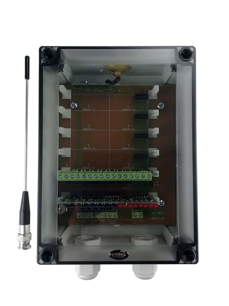
Receiver with link supervision at the depot: from each site it receives two states and monitors the link and the transmitter’s power. The basic version handles 2 sites.
Quantity: 1
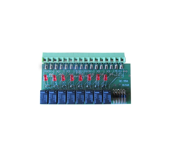
Receiver expansion module: adds pumping stations 3 and 4. Further modules extend the system to 10 sites without replacing the receiver.
Quantity: 1
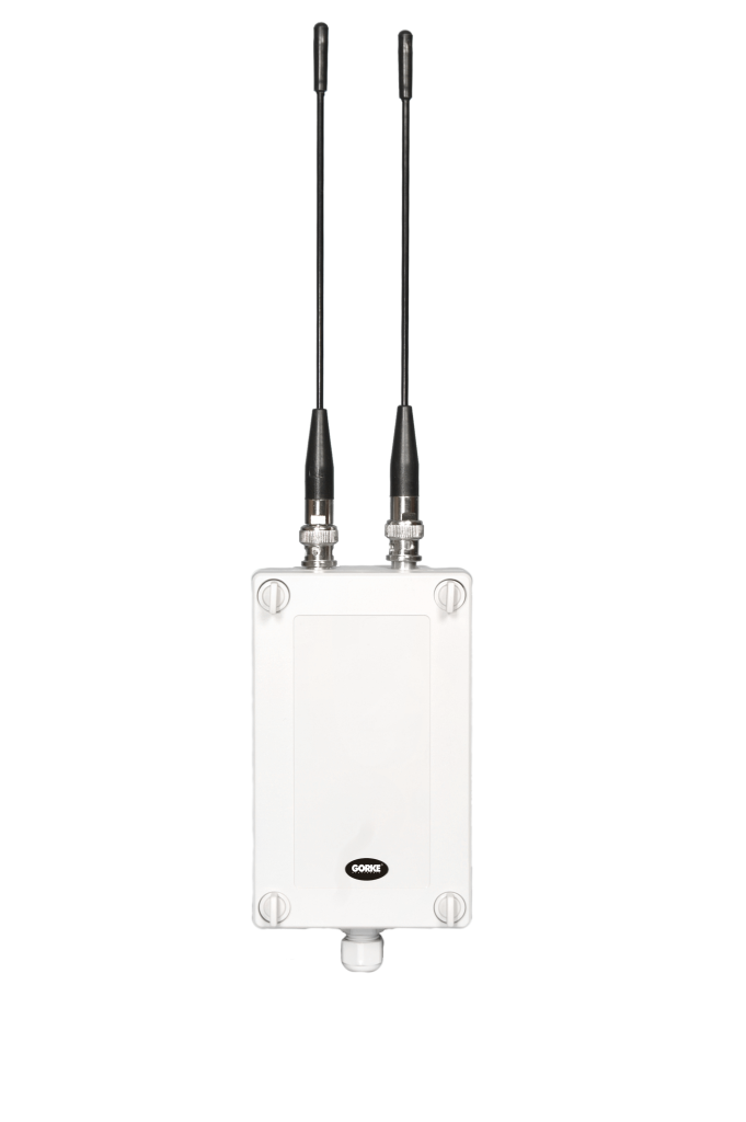
Repeater with link supervision on the route to the farthest pumping station — it extends the range by about a kilometre. Powered at 12 V DC.
Quantity: 1
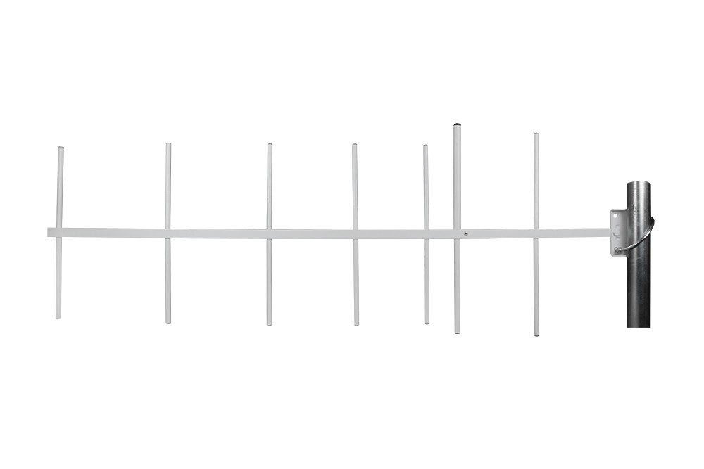
11.5 dBi Yagi directional antenna at a transmitter or the repeater, aimed at the depot wherever the radio test shows a weak signal.
Quantity: per radio test
GSM transmitter in a housing with a power supply, at the depot: it turns the states on the receiver’s outputs into a text message to the on-call worker — important above all after hours, when nobody is at the depot.
Quantity: 1
Powers the transmitter in each pumping station, the repeater and the receiver at the depot — also during a mains failure in a storm.
Quantity: 6
Catalogue figures describe a device under stated conditions, usually in open terrain, and are not a guaranteed range in every installation. Device quantities in the examples are indicative.
04 / Value for the investor
The receiver tells high level, pump fault, broken link and lost power apart — silence from a pumping station does not pass for calm.
The text message reaches the on-call worker in the field, so an alarm from the pumping station under the viaduct does not wait until the depot opens in the morning.
Further pumping stations are added with expansion modules — up to 10 sites on one receiver, without replacing the equipment at the depot.
05 / Before installation
Before devices are chosen, what matters is the site’s conditions and how the system ties into the final installation.
Example configuration — it needs a technical selection for your site.
More from this sector
Water and municipalities
A municipality: the dispatcher sees a tank-full alarm, switches the pump on remotely and receives a confirmation from the pumping station that it has been switched on — by radio, over 1.5 km of urban area.
A project for your site
Send us the key requirements — GORKE will help define the scope, the technology and the components that fit the investment.