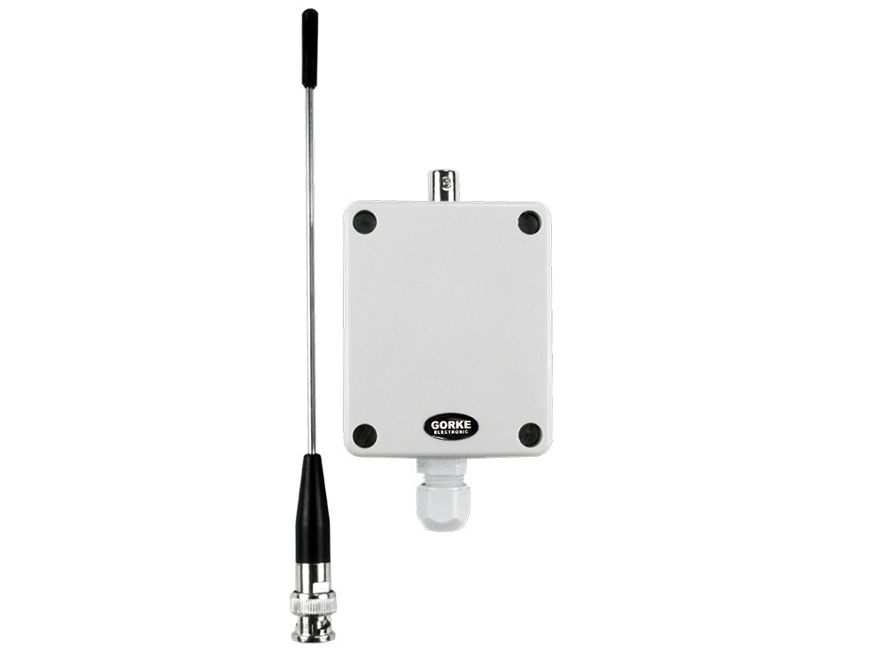
NRP-102K
Transmitter with link supervision at the tank, 12 V DC: channel 1 — tank-full alarm from the float switch, channel 2 — pump switch-on confirmation. It also sends link and power supervision signals.
Quantity: 1 per pumping station
A wireless installation with link supervision between the control room and the pumping stations, about 1.5 km through an urban area: a level alarm from the tank, a pump start command and a confirmation that the pump has been switched on.
01 / Investment context
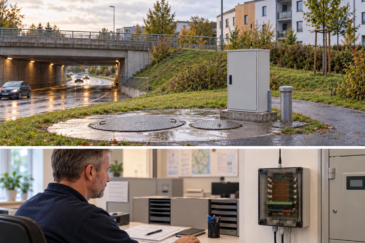
The municipality operates sewage pumping stations within the town. The control room responsible for them is about 1.5 km from the tanks, with urban buildings in between.
The dispatcher needs to know when the sewage in a tank reaches the permitted level, and then be able to switch the pump on remotely. An overflowing tank means sewage spilling out — damage to the surroundings and the cost of cleaning up.
The basic requirement was a wireless installation able to cover this distance. And sending a command is not enough: the dispatcher must get a confirmation from the pumping station that the pump has been switched on, not just know that a signal has left the control room.
The investor’s goal: To monitor the sewage level in the tanks and switch the pumps on and off remotely — by radio, over a distance of about 1.5 km through an urban area.
A float switch monitors the sewage level in the tank. A transmitter with link supervision (NRP-102K) works at the tank: channel 1 carries the tank-full alarm from the float switch, channel 2 the confirmation that the pump has been switched on. The transmitter also sends link and power supervision signals, so the receiver in the control room (RP10-2K) knows when the link is broken — the absence of a signal is information too.
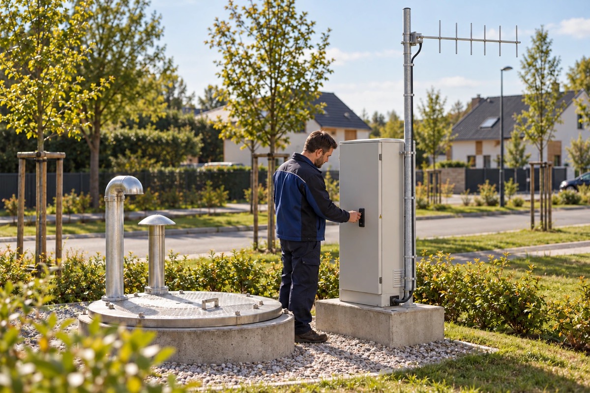
After a tank-full alarm, the dispatcher triggers the transmitter installed in the control room (NRP-102), which sends its command when supply voltage is applied to it. The command is received by a high-sensitivity receiver at the pump (OPC-K01), and its relay in the control circuit switches the pump on. The motor is fed through a contactor with the pump’s protection devices, not by the receiver itself.
Channel 2 of the transmitter at the tank confirms to the control room that the pump has been switched on. The dispatcher therefore does not have to assume that the command worked — the signal comes from the pumping station. Directional antennas made the link work over about 1.5 km through the urban area; in today’s range this is the AYK-437 Yagi antenna.
02 / Operating principle
The dispatcher receives a level alarm from the tank by radio, switches the pump on remotely and gets a confirmation from the pumping station.
01 / Signal source
NRP-102K Transmitter at the tankChannel 1 carries the tank-full alarm from the float switch, channel 2 the pump switch-on.
02 / Reception
RP10-2K Receiver in the control roomReceives both states and monitors the link and the transmitter’s power.
03 / Notification
Dispatcher Municipal control roomSees the tank-full alarm, and then the confirmation that the pump has been switched on.
The dispatcher also learns of a broken link. The transmitter sends link and power supervision signals, so the absence of a signal is information too.
01 / Signal source
NRP-102 Transmitter in the control roomThe dispatcher applies power to it, and it sends the command.
02 / Reception
OPC-K01 Receiver at the pumpReceives the command, and its relay in the control circuit switches the pump on.
03 / Action
Pump At the pumping stationThe motor is fed through a contactor with its protection devices, not by the receiver.
The confirmation comes from the pumping station. The dispatcher does not have to assume the command worked — channel 2 of the transmitter at the tank reports that the pump has been switched on.
A simplified functional diagram.
03 / Installation components
The devices named in the description of the installation.
Transmitter with link supervision at the tank, 12 V DC: channel 1 — tank-full alarm from the float switch, channel 2 — pump switch-on confirmation. It also sends link and power supervision signals.
Quantity: 1 per pumping station
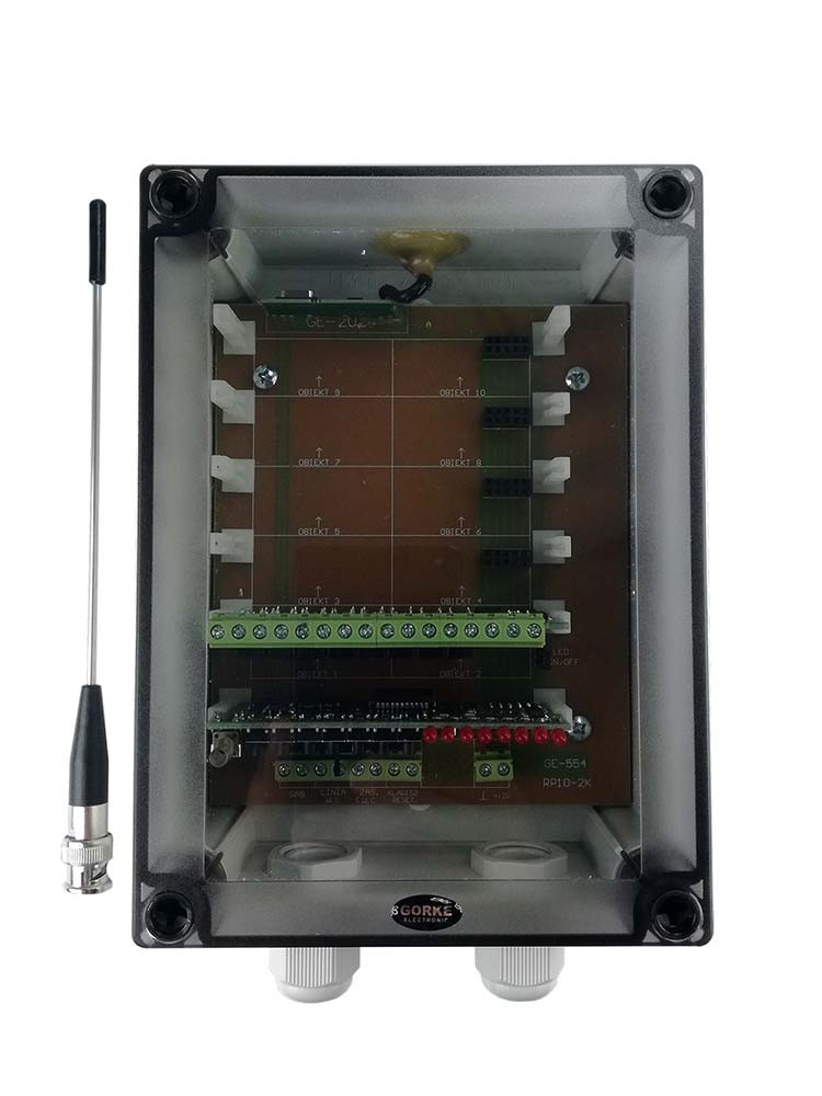
Receiver with link supervision in the control room: from each site it receives both states and monitors the link and the transmitter’s power, reporting a broken link like an alarm.
Quantity: 1
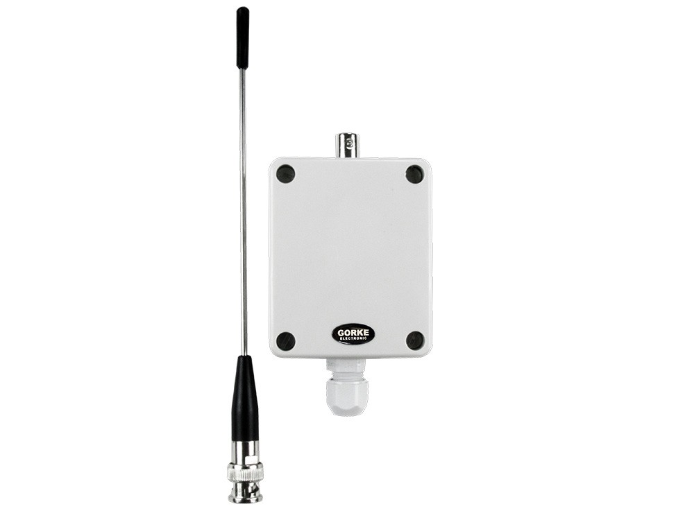
The dispatcher’s transmitter in the control room: it sends the pump switch-on command when the dispatcher applies supply voltage to it.
Quantity: 1 per pumping station
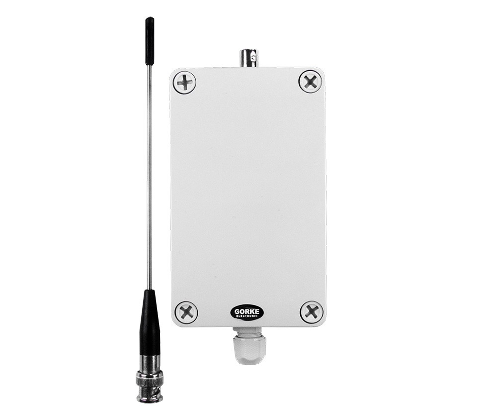
High-sensitivity receiver (H2 module) at the pump: on the command from the control room, its relay in the control circuit switches the pump on.
Quantity: 1 per pumping station
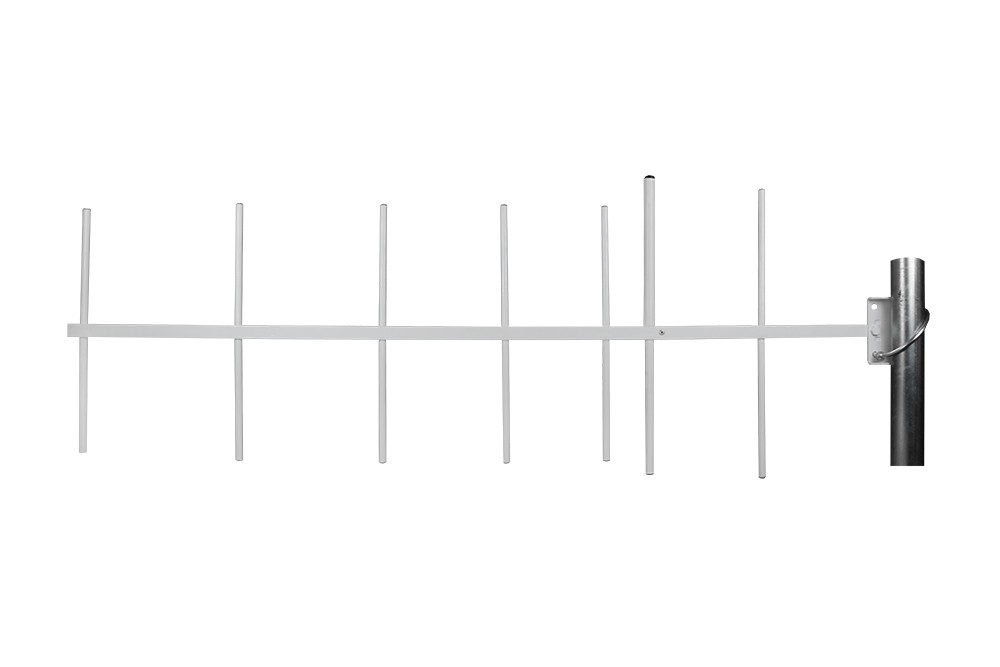
11.5 dBi Yagi directional antenna — today’s equivalent of the directional antennas that provided the range through the urban area.
Quantity: per radio route
Catalogue figures describe a device under stated conditions, usually in open terrain, and are not a guaranteed range in every installation. Device quantities in the examples are indicative.
04 / Value for the investor
The dispatcher does not stop at sending the command: the second channel of the transmitter at the tank reports that the pump has been switched on.
Supervision of the link and the transmitter’s power means that a broken link is reported like an alarm instead of looking like a quiet night.
The municipality’s own radio link connects the control room and the pumping stations — no cable laid through the built-up area and no subscription for the transmission.
05 / Before installation
Before devices are chosen, what matters is the site’s conditions and how the system ties into the final installation.
Source: an archived GORKE description of the installation. For a new investment we choose current models.
More from this sector
Water and municipalities
A municipal utility monitors four stormwater pumping stations by radio: high water level and pump faults reach the depot, and a broken link is reported like an alarm.
A project for your site
Send us the key requirements — GORKE will help define the scope, the technology and the components that fit the investment.